Getting Started
The WattWächter WiFi/USB arrives fully assembled with pre-installed software. For setup you need:
- A Wi-Fi-capable device (smartphone, tablet, or PC)
- Your Wi-Fi credentials
- A digital electricity meter (smart meter or eHz) with PIN from your grid operator
1. Select Operating Mode
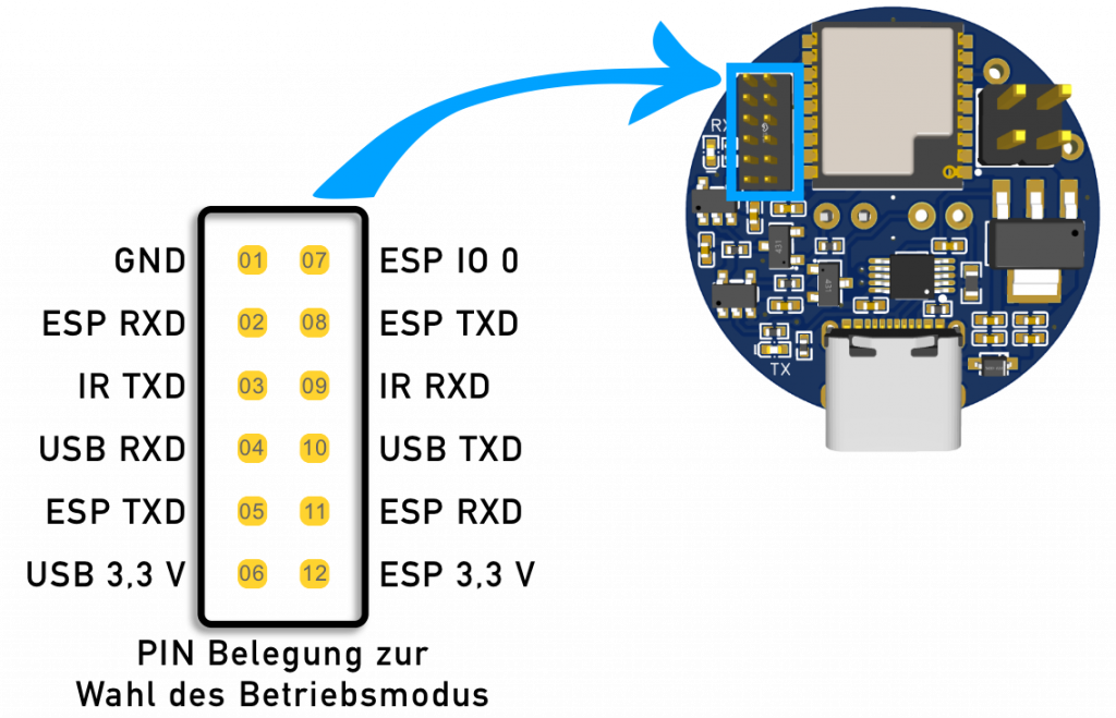
The WattWächter supports two operating modes: Wi-Fi and USB. Wi-Fi mode is pre-configured at the factory. The mode is set via jumper positions on the circuit board.
Warning
Always disconnect the power supply before opening the housing!
PIN assignment for operating modes:
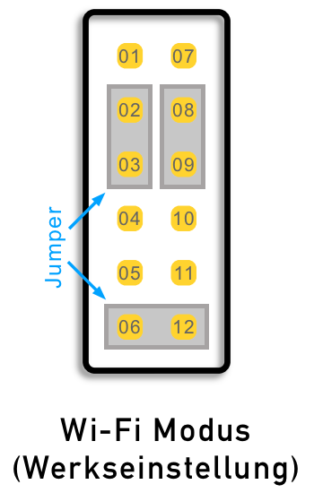
Wi-Fi Mode (factory default)
In Wi-Fi mode, the WattWächter connects to your existing Wi-Fi network. Data can be retrieved via web browser or MQTT.
Jumper positions:
- PIN 02 & 03
- PIN 08 & 09
- PIN 06 & 12
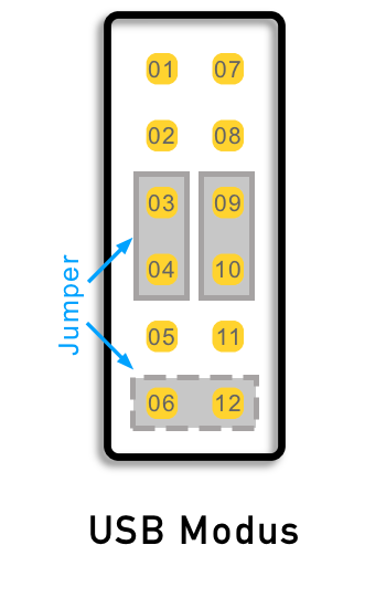
USB Mode
In USB mode, the WattWächter transmits data directly via USB-C to a computer or Raspberry Pi. The USB cable serves as both power supply and data connection.
Jumper positions:
- PIN 03 & 04
- PIN 09 & 10
- Optional: PIN 06 & 12
2. Connect Power Supply
Connect the WattWächter via a USB-C cable to a power adapter (5 V, min. 500 mA, max. 15 W) or a battery pack. The blue LED (RX) lights up continuously once the WattWächter is powered.
Power banks not recommended
Conventional power banks often have an auto-shutoff feature that deactivates the output at low power draw (< 0.5 W). Use a battery pack without auto-shutoff instead.
USB Mode
In USB mode, the USB-C cable serves as both power supply and data connection.
3. Set Up Wi-Fi
After powering on, the WattWächter creates its own Wi-Fi network named "WattWaechter-..." (followed by an alphanumeric identifier).
- Connect to this network (no password required)
- Open a web browser and navigate to 192.168.4.1
- Select your local Wi-Fi network and enter the password
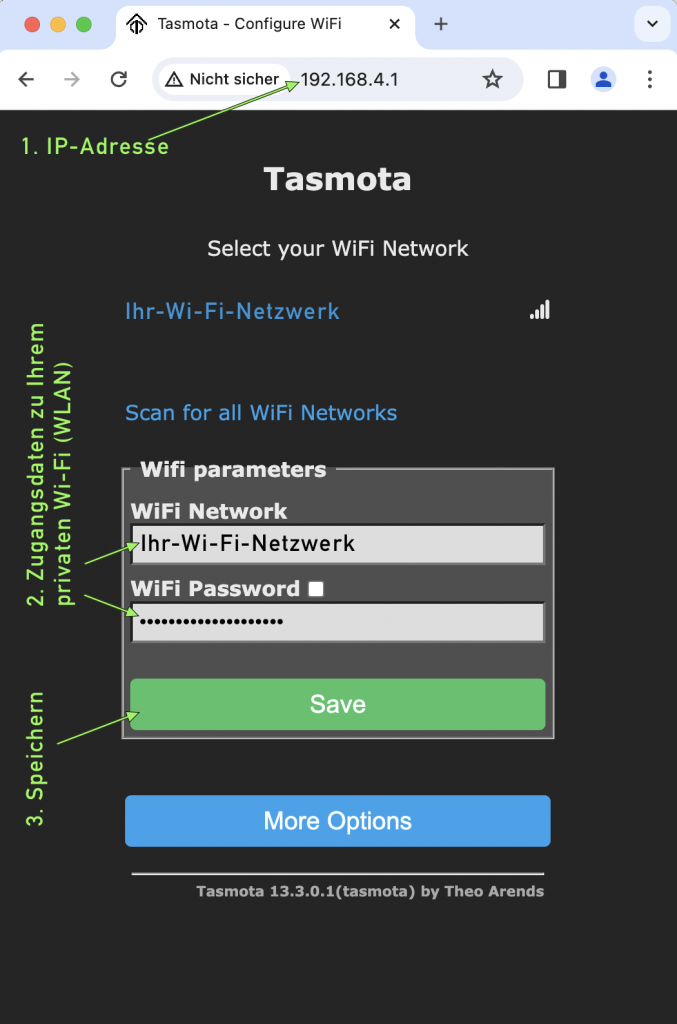
After a successful connection, the WattWächter displays its new local IP address.
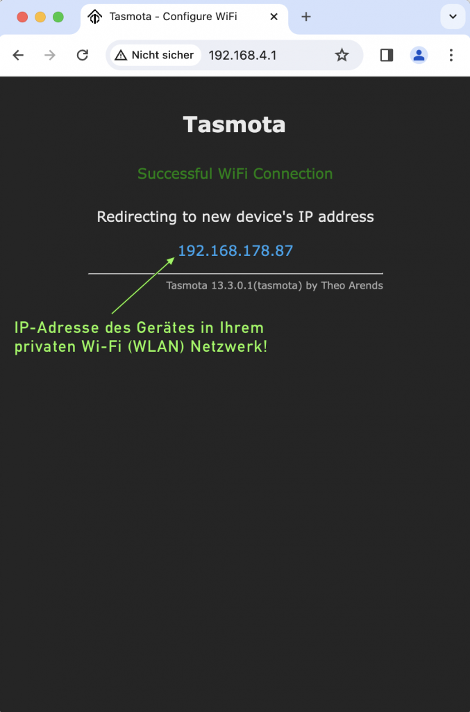
Tip
Write down the displayed IP address – you'll use it to access the WattWächter's web interface on your local network.
4. Configure Meter Script
Depending on your meter type, a matching script needs to be configured. An overview of available scripts can be found at Meter Scripts.
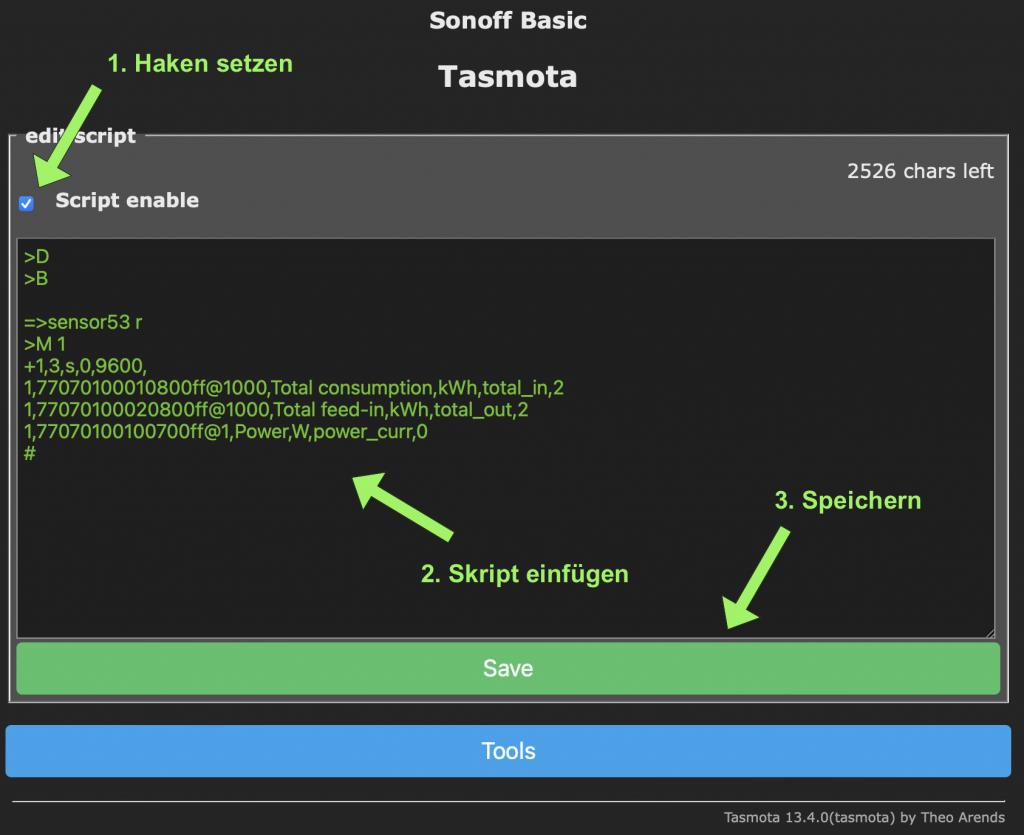
- Open the WattWächter's web interface using the IP address noted earlier
- Navigate to Tools → Edit Script
- Enable the Script enable checkbox
- Paste the complete script for your meter type
- Click Save
5. Position the Sensor Head
The WattWächter attaches magnetically to the meter. Position it directly over the IR interface (infrared diodes) of your smart meter – typically with the cable facing upward.
PIN activation required
For your meter to transmit measurement data via infrared, the extended data display must be activated on the meter. You need the PIN code from your grid operator. Enter it directly on the meter, then set PIN to Off and Inf to On in the meter menu.
Once everything is set up correctly, the measurement values will be displayed in the WattWächter's web interface.